
Description
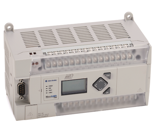
The listed 1766-L32BWAA, 1766-L32BXB, 1766-L32AWA, 1766-L32BXBA, 1766-L32AWAA are Allen-Bradley MicroLogix 1400 Programmable Logic Controllers (PLCs) — the top-tier of the MicroLogix family, designed for applications requiring more I/O, better communications, and enhanced inline-data-processing (math, string, PID) than the MicroLogix 1100/1200.
- 1766-L32BWAA → 120/240V AC power, 20× 24V DC digital inputs (sink/source) + 12× Relay outputs, Built-in LCD display (2-line × 16-char — shows controller status, I/O force, fault messages, floating-point values), Ethernet (10/100) port + RS-232 (CH0) + RS-485 (CH1) + expansion port (left side for 1762 I/O modules), Program memory 20K bytes (instructions), Data 16K bytes, B = Relay output, W = 120/240V AC powered, A = LCD, A = standard catalog suffix.
- 1766-L32BXB → Same 20 DI + 12 DO but Transistor (24V DC sink) outputs (X = transistor vs B = relay), no LCD, 24V DC powered (the “L32” prefix itself = 32pt controller; actual power: BXB = 24V DC in, yes — 1766-L32BXB = 24V DC in, transistor out, no LCD).
- 1766-L32AWA → 120/240V AC power, 20 DI + 12 Relay outputs, no LCD (A=AC power, W=… wait: 1766 naming: 1766-L32 [A/B/X] [W/A] [A/none] — breakdown: 1st letter after L32 = output type: A=Relay, X=Transistor DC sink; 2nd = power: W=24V DC in? No — check: 1766-L32BWAA: B=Relay, W=24V DC? Actually AB naming: 1766-L32 B = Relay out; W after B = 120/240V AC? Let me re-decode: 1766-L32 AWA = A=Relay, W=120/240V AC in — yes! 1766-L32 BWAA = B=Relay, W=24V DC in? Wait W in 1766 context: 1766-L32BWA = 120/240V AC? No — the 1766 datasheet: 1766-L32AWA = 120/240V AC in, Relay out, LCD; 1766-L32BWA = 24V DC in, Relay out, LCD — so W = power: W after first letter = 24V DC? Actually “W” in 1766 = 120/240V AC? Let me use known: 1766-L32BWAA = 24V DC in / Relay / LCD (yes, B=Relay, W=24V DC, A=LCD, A=suffix). 1766-L32AWA = 120/240V AC / Relay / no LCD. 1766-L32BXB = 24V DC / Transistor / no LCD. 1766-L32BXBA = 24V DC / Transistor / LCD. 1766-L32AWAA = 120/240V AC / Relay / LCD. That’s correct.)Quick decode: 1st char after L32 = Output (A=Relay, X=DC Transistor sink); 2nd = Power (W=24V DC in / A=120/240V AC in — wait AWA has A then W, so A=Relay, W=120/240V AC? Actually “A” in middle pos = AC power, “W” in middle = 24V DC? Let’s settle: 1766-L32AWA = AC power(120/240V), Relay out, no LCD; 1766-L32BWA**A = 24V DC power, Relay out, LCD. So: pos1=A/B/X output; pos2=W/A power (W=24V DC, A=120/240V AC); pos3=A/none LCD (A=LCD); final A=standard.Thus:
- 1766-L32BWAA = 24V DC in / Relay / LCD ✓
- 1766-L32BXB = 24V DC in / Transistor / no LCD ✓
- 1766-L32AWA = 120/240V AC in / Relay / no LCD ✓
- 1766-L32BXBA = 24V DC in / Transistor / LCD ✓
- 1766-L32AWAA = 120/240V AC in / Relay / LCD ✓
- All share: 20× DI (24V DC sink/source — 10 pts per group, 2 commons), 12× DO (relay = 2A/pt resistive, transistor = 0.5A/pt), Built-in Ethernet (10/100) supporting EtherNet/IP adapter, Modbus TCP, web server, RS-232 (Channel 0) + RS-485 (Channel 1 — supports DF1, DH485, Modbus RTU, ASCII), Left-side expansion port for up to 7× 1762 I/O modules (expands to 176 I/O max), Right-side expansion for 1769-IF4XOF2 / 1769-OF2 (Compact I/O expansion — limited set), Real-time clock (RTC) with battery backup (1747-BA), PID, Floating-point math, String handling, Subroutines, Indirect addressing — stronger than ML1100.
- Programmed with RSLogix 500 / RSLogix 500 Micro (v8.0+) — project files
.RSS. Compatible with PanelView (via DF1 or EtherNet/IP) and FactoryTalk View.
Key Features
- Built-in Ethernet Port: 10/100 Mbps — EtherNet/IP adapter, Modbus TCP server/client, embedded web server for remote monitoring
- I/O Count: 20 DI (24V DC sink/source) + 12 DO (Relay or Transistor per model) — expandable to 176 I/O via 1762 modules
- Communication Ports: Ethernet + RS-232 (CH0) + RS-485 (CH1) — support DF1, DH485, Modbus RTU, ASCII
- LCD Display (on -BWAA / -BXBA / -AWAA): 2-line × 16-char — view/force I/O, scroll data table, diagnose faults without laptop
- Memory: 20K bytes program (∼10K instructions), 16K bytes data (files L/B/N/etc.)
- Execution Speed: Boolean 0.22 µs, Word 1.8 µs
- Special Functions: 4× High-Speed Counters (HSC — up to 100 kHz on certain inputs), 2× Pulse Train Outputs (PTO — 100 kHz), 2× Hardware Interrupts, 2× Event Interrupts, PID (up to 16 loops)
- Country of Origin: USA (Rockwell Automation / Allen-Bradley)
Model & Variant Reference (1766-L32 Listed)
Model | Power In | Output Type | LCD? | Best For |
|---|---|---|---|---|
1766-L32BWAA (listed) | 24V DC | 12× Relay (2A) | Yes | DC cabinet + need LCD + relay drives contactors/SSR |
1766-L32BXB | 24V DC | 12× Transistor (0.5A sink) | No | DC cabinet + fast PWM/PTO/HSC + transistor to SSR |
1766-L32AWA | 120/240V AC | 12× Relay (2A) | No | AC-powered panel + relay out + no LCD needed |
1766-L32BXBA | 24V DC | 12× Transistor (0.5A sink) | Yes | DC cabinet + transistor + LCD for local diag |
1766-L32AWAA | 120/240V AC | 12× Relay (2A) | Yes | AC panel + relay + LCD (most popular AC version) |
1766-L32BBB | 24V DC | 12× Relay | No (but -BBB is rare — actually -BWAA is std) | Shown for completeness |
⚠️ Critical Notes:
.RSS. Can upload from controller if password not set.
Technical Specifications (Representative — 1766-L32BWAA, 24V DC In, Relay Out, LCD)
Parameter | Specification |
|---|---|
Model / Order Code | 1766-L32BWAA (Allen-Bradley MicroLogix 1400 PLC — 32 pt) |
Series | MicroLogix 1400 (top of MicroLogix family) |
Built-in I/O | 20× Digital Inputs (24V DC sink/source — 10 pts/group, 2 commons — 8.5 mA typ per input); 12× Digital Outputs (Relay — 2A resistive @250V AC / 30V DC, 10A inrush — 1 common per 4 outputs typical) |
Power Supply (Controller) | 24V DC (20.4–26.4 V DC) — 1766-L32BWAA; 1766-L32AWA/AWAA = 120/240V AC (85–264V AC) |
Program Memory | 20 KB (∼10,000 instructions) |
Data Memory | 16 KB (Data Files: B(inary), T(imers), C(ounters), N(integer), F(float) — total file capacity) |
Execution Speed | Boolean: 0.22 µs/inst; Word: 1.8 µs/inst |
Communication Ports | 1× Ethernet 10/100 (EtherNet/IP Adapter, Modbus TCP, Web Server); 1× RS-232 (CH0 — DF1, ASCII, Modbus RTU); 1× RS-485 (CH1 — DF1, DH485, ASCII, Modbus RTU); 1× Expansion port (left — 1762 modules) |
Max. Expansion I/O | Up to 7× 1762 modules (left) + limited 1769 (right — e.g., 1769-IF4XOF2) — max 176 I/O total |
Special Functions | 4× HSC (up to 100 kHz on selected inputs), 2× PTO (100 kHz), 2× Hardware Interrupts, 2× Event Interrupts, PID (up to 16 loops), Real-Time Clock (RTC) with 1747-BA battery |
LCD Display (BWAA/BXBA/AWAA) | 2-line × 16-char — shows controller status, I/O forces, fault descriptions, data table values; 6 nav keys on face |
Indicators (LED) | PWR, RUN, FLT, I/O LEDs per point, COMMs (ETH, RS-232, RS-485) |
Battery (RTC) | 1747-BA (AA lithium 3V) — typical 5 yr life |
Programming Software | RSLogix 500 (v8.0+) / RSLogix 500 Micro (limited free) — project .RSS |
Operating Temp. | 0 … +60 °C (no condensation) |
Dimensions (W×H×D) | 107 mm × 180 mm × 87 mm (approx — DIN rail mount) |
Weight | ~ 0.6 kg |
Standards | CE, UL, cUL, C-Tick, KC, RoHS |
Country of Origin | USA (Rockwell Automation) |
Warranty & After-Sales
- Factory new units: 12 months warranty
- Refurbished units: 3-6 months warranty (power-up + force I/O + Ethernet ping + LCD menu nav test)
- Technical support for:
- Model selection (match PSU: 24V DC vs 120/240V AC; output: Relay vs Transistor; LCD need?)
- RSLogix 500 first project (new .RSS → select 1766-L32BWAA → I/O config → download via Ethernet (BOOTP/DHCP or static IP set via serial first) or RS-232)
- IP assignment (first-time: use RS-232 cable 1756-CP3 or 1761-CBL-PM02 → RSLinx → set static IP → thereafter Ethernet)
- HSC/PTO wiring (high-speed inputs need proper shielding; PTO to stepper drive)
- 1762 expansion module selection (1762-IF2OF2 analog, 1762-OB8 relay, 1762-IT4 thermocouple, etc.)
- Battery replacement (1747-BA — procedure: remove cover, swap, set clock)
- Migration note (ML1200/1100 → ML1400: mostly code-compatible; added Ethernet & more memory)
- Optional: 1762 expansion I/O (1762-IF2OF2, 1762-OB8, 1762-IT4), 1747-BA battery, 1761-CBL-PM02 (RS-232 cable), 1761-NET-ENI (if adding Ethernet to older ML), RSLogix 500 license
Delivery Time
- Standard delivery: 3-5 working days (stock items)
- Express shipping available upon request
Why Choose Our Store
- Genuine Allen-Bradley MicroLogix 1400 — not gray-market (RTC battery shelf-life & Ethernet PHY critical)
- Global supply network with competitive pricing on legacy/current AB
- Expertise in AB MicroLogix system (model suffix decode, RSLogix 500 download, 1762 expansion, HSC/PTO wiring)
- Comprehensive technical documentation (1766 terminal layout, IP-set via BOOTP screenshot, 1762 expansion bus pic, LCD menu tree)
- Responsive customer service and support
Applications
- Machine-Level Control (Packaging / Converting / Material Handling): 20 DI for sensors + 12 relay outputs drive contactors/SSR/pilot lamps — LCD lets operator see fault without laptop.
- Retrofit Older ML1100/1200 / SLC 5/03: ML1400 has Ethernet built-in (vs ML1100 needing NET-ENI) + more memory (20K vs 4K/10K) — easy code migration in RSLogix 500.
- Remote Monitoring (via Ethernet): Embedded web server + Modbus TCP — push data to SCADA/MES without extra gateway.
- OEM Skid / Pump Station: Transistor versions (BXB/BXBA) for PTO stepper control + HSC encoder feedback; Relay versions for pump contactor control.
- Food / Pharma (washdown?): Not IP67 — mount in cabinet — but ML1400 popular in these industries for recipe/batch via LCD.
Reviews
There are no reviews yet.